There is a way of doing per-pixel logic such as what you want, by using Blending Modes. Basically the different transfer modes in AE can be though of as Boolean logic operations that go on at the pixel level. The different transfer modes are spelled out here.
So I think I've worked out how you'd do it.
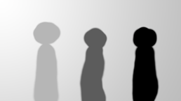
Here are the images I'm using: two depth maps and two colour maps:
Picture 1 and depth matte

Picture 2 and depth matte

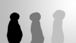
As you can see, no expense was spared with the render.
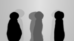
OK so in AE I make a comp with just the depth mattes in it. I set the blending mode of the top layer to Darker Color.

The darker color blending mode does this logic on each pixel:
(luminosity of this layer < luma of layer(s) below)? This layer: lower layer
This means the darker object will appear wherever two objects overlap That gives me this result:
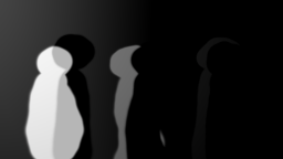
Now we have to turn this into a matte for picture 1, where the black will be opaque and white transparent. To get rid of the parts of the comp that aren't relevant to picture 1 I put this comp into a new comp, along with another copy of depth matte 1, which I put on top.

I set the blending mode of the top one to Difference which can be though of as:
(this layer == lower layer)? 0: abs(this layer - lower layer)
and this is the result:
OK, now I put this comp in a new comp with my colour images. This comp goes above image 1.
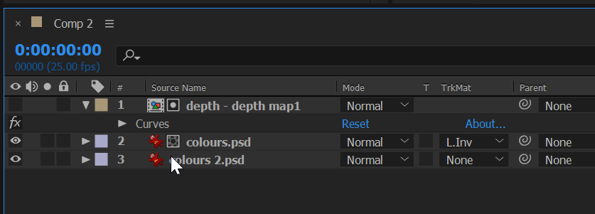
In this final comp I set the depth map comp as a Luma inverted matte for picture 1. Note that when you do that it turns off the visibility for that layer (see the eye icon is disabled on the top layer). This is the result:
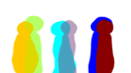
Obviously there's a bit of a problem in that there are semi-opaque areas. So I need some sort of threshold. I could do this a few ways, but the way I like is with the curves effect. I apply curves to the top layer (the depth matte layer) like so:
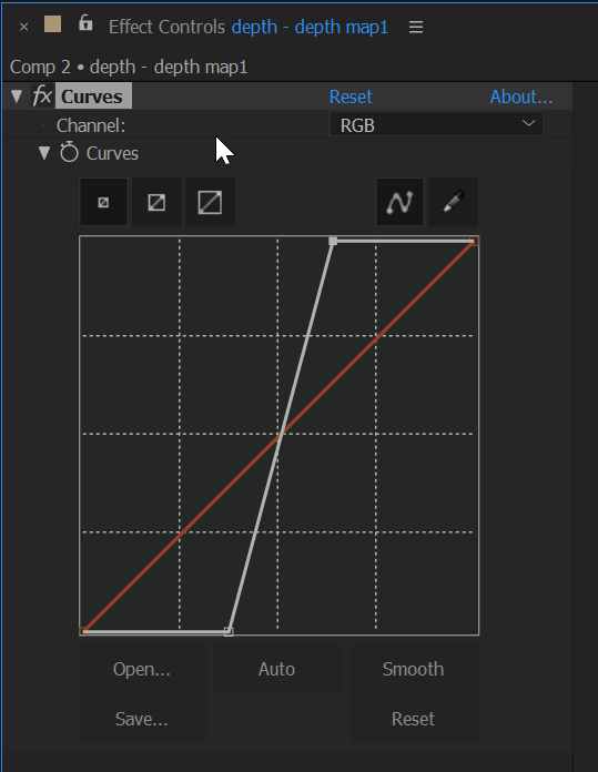
I originally set this to be a hard step at 50%, but that makes the edges of the matte super sharp, so I made it slope a bit around the mid-point. You can play with this to get it right. That's the advantage of using Curves instead of say the Threshold effect.
Finally I got this result, with the figures correctly sorted on the "z" axis:
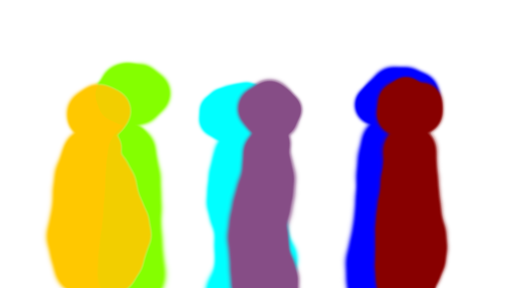
I hope this all makes sense, and that it works in real life. Thanks for the question, it was an interesting exercise.


